How to Connect LEDs using One or Multiple Arduino Pins
Step-by-step tutorial on connecting LED lights to Arduino with schematics, breadboard diagrams, and code examples.
This tutorial has everything you need to know about connecting LED lights using an Arduino. We are going to go over the components needed for this tutorial and go over different variations on how to connect LEDs to Arduino.
This tutorial is intended to be beginner-friendly with thorough explanations guided with diagrams and examples to help you understand about using LED lights with Arduino whenever you need to work on more advanced projects.
What Materials You Will Need
Hardware
| Set of 5mm LED Lights | x 1 | ||
| Breadboard | x 1 | ||
| Set of Jumper Wires | x 1 | ||
| Arduino Uno R3 | x 1 | ||
| Arduino UNO USB Data Sync Cable | x 1 | ||
| Set of 220 Ohm Resistors | x 1 |
Software
| Arduino IDE |
How to Connect an LED without using an Arduino Pin
In this first tutorial, you will learn a basic way to connect an LED using an Arduino without having to program it.
Schematic Diagram
Let's look at the schematic diagram first prior to connecting the circuit.

The circuit is simple. Arduino is the power supply providing a 5V as long as you connect it to the 5V pin. Notice Arduino has also a 3.3V pin. For this circuit, we will use the 5V.
Don't Kill The LED Light
Then, we use a 220Ω resistor prior to connecting the LED light. The reason we do this is to drop the voltage coming from the power supply to feed the LED light.
Typically, LEDs work with a voltage within a range of 1.8V and 3.3V based on the color. The LEDs suggested in the Hardware section the following manufacturer's specifications:
- Red and Yellow LEDs: 2V - 2.2V
- White, Green, and Blue LEDs: 3V - 3.2V
If you connect an LED light with a voltage that exceeds its maximum voltage range, it will kill the LED, and you will need to use another LED light.
The 220Ω resistor drops the voltage to 3V and the red LED light uses 2V. This is correct as the total voltage of a series circuit is equal to the sum of all of the individual voltages. Taking that as a reference, the voltage across the resistor and the voltage across the LED should be equal to the voltage coming from the power supply (Arduino).
Arduino Voltage = Voltage across 220Ω Resistor + Voltage across Red LED
5V = 3V + 2V
Connect the LED Light Correctly
LED lights have two terminals, one of the terminals is the anode and the other is the cathode. The anode is electrodes positively (+) charged. The cathode is electrodes negatively (-) charged.
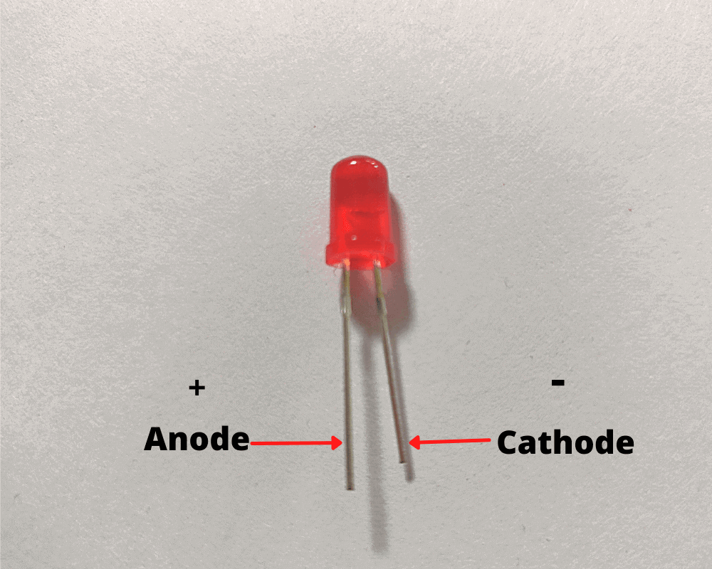
LEDs anode and cathode terminals can be recognized because of their length:
- LED anode terminal is the longest terminal
- LED cathode terminal is the shortest terminal and it not straight as the anode terminal.
Why is this important to know?
Because based on the way the terminals of the LED are connected in the circuit, it will either make the LED turn on or not. Hence, whenever you connect the LED in the circuit. Make sure to connect the cathode terminal to the ground and the anode terminal to the wire of resistance after the voltage is dropped.
Breadboard Diagram
Now, you are ready to connect this basic circuit. Below, you will see the diagram of how the circuit should look once everything is connected.

Note: Make sure to connect the Arduino UNO USB Data Sync Cable between the Arduino and the computer to provide a power supply to the circuit.
Result
Here's the final result of how it turned out for me.
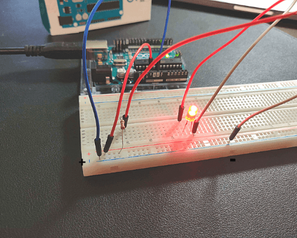
Congratulations! You have made your first circuit!
While using Arduino as a power supply seems overkill as Arduino is capable of much more, it shows us the foundational knowledge and understanding of how to turn on an LED light. However, it is time for us to start using the Arduino pins and programmatically turn on the LED.
How to Connect an LED using an Arduino Pin
Now that you understand the foundation, let's use an Arduino pin to turn on the LED light. We are going to make small changes from the original circuit as well as start writing small pieces of code to turn on the LED light.
Schematic Diagram
This is the schematic diagram of the circuit we are going to build.

Taking as a reference the schematic diagram, we are going to do the following:
- Connect the Arduino Digital Pin 2 to one wire of the 220Ω resistor
- Connect the other wire of the 220Ω resistor to the anode (+) terminal of the LED light
- Connect the cathode (-) terminal of the LED light to the GND or ground pin of the Arduino
Breadboard Diagram
Below, you will see the diagram of how the circuit should look once everything is connected.

Notice how the only difference with respect to the LED without using an Arduino Pin circuit is that the power supply comes from the digital pin 2 instead of the 5V port.
Upload the Code
If you haven't installed Arduino IDE on your computer, download it and install the software.
Once installed, open the software and create a new project by clicking on File on the menu, and then select the New option.
Now, copy the code below and paste it into your Arduino project.
/*
 *  Connect an LED using an Arduino PIUN.
 *
 *  For more guides and tutorials: https://www.thecircuitmaker.com
 */

// set up a variable to store the pin number that will turn on the LED light
int ledPin = 2;

void setup(){
  // configure the LED pin to behave as OUTPUT mode to send HIGH or LOW signals
  pinMode(ledPin, OUTPUT);
}

void loop()
{
   // turn on the LED
   digitalWrite(2, HIGH);

   // wait for 1 second
   delay(1000);

   // turn off the LED
   digitalWrite(2, LOW);

   // wait for one second
   delay(1000);
}
Finally, upload the code to Arduino. To do so, make sure to have the Arduino connected to your computer using Arduino UNO USB Data Sync Cable. Then, go to the Arduino IDE and click on the menu option Sketch and select the option Upload.
Understanding the Code
First, I define a variable called ledPin to store the digital pin number I want to use to send signals to turn on or off the LED light. You can update the pin number between 1 to 13. However, if you decide to do so, you must update the wire of the circuit to use whichever pin number you selected in Arduino.
// set up a variable to store the pin number that will turn on the LED light
int ledPin = 2;
In the setup function of the code, we configure the ledPin as OUTPUT mode using the pinMode function. In Arduino, you can set up different pin modes: INPUT, OUTPUT, or INPUT_PULLUP. We use the OUTPUT mode, which means we can provide a substantial amount of current to other circuits.
void setup(){
  // configure the LED pin to behave as OUTPUT mode to send HIGH or LOW signals
  pinMode(ledPin, OUTPUT);
}
Finally, in the loop section, we program the logic that turns on and off the LED. When we use the digitalWrite function using HIGH, which means the voltage coming out from a specific pin number will be 5V.
Then, we wait for 1 second using the delay function.
After one second, we change the voltage from the pin we previously defined to zero using the option LOW.
Then, we wait another second using the delay function.
In the loop section, the code will run over and over once it executes all of the statements. Hence, after changing the voltage to zero, and then waiting for a second, the code will execute all over from the beginning of the loop function, repeating the cycle.
void loop()
{
   // turn on the LED
   digitalWrite(ledPin, HIGH);

   // wait for 1 second
   delay(1000);

   // turn off the LED
   digitalWrite(ledPin, LOW);

   // wait for one second
   delay(1000);
}
Result
Your LED should be blinking every second. If it is not working, feel free to recheck the steps one more time and verify the code is correctly uploaded to Arduino.
How to Connect Multiple LEDs using Multiple Arduino Pins
Now that we know how to connect an LED using an Arduino pin. It is time for us to connect multiple LEDs using multiple Arduino Pins. The circuit and the code logic are different from the previous tutorial where we connect an LED using an Arduino pin. However, most of the logic and circuit diagrams use the same foundation.
Breadboard Diagram
Below, you will find the circuit we are going to wire up. Check it out first, and then I'll explain what you need to do.

- Use a jumper wire to connect the blue power rail of the breadboard with one of the GND pins of Arduino
- Get twelve LED lights
- Connect the cathode (-) terminal of each LED in the blue power rail of the breadboard
- Connect the anode (+) terminal of each LED in the a separate terminal strip (5 hole rows)
- Get twelve resistors of 220Ω
- Connect one connecting lead of the each resistor to the one of the same terminal strip where the anode (+) terminal of each LED is connected
- Connect the other connecting lead of each resistor to a terminal strip that hasn't been used
- Use jumper wires to connect one of the resistors to one of digital pins of Arduino. We are using digitals pins 2, 3, 4, 5, 6, 7, 8, 9, 10, 11, 12, and 13
- In that way, you should have one digital pin connected to one 220Ω resistor, which is also connected to an LED and its cathode (-) terminal is connected to the negative power rail of the breadboard
Upload the Code
Now, copy the following code and paste it into the Arduino IDE project. Inside the Arduino IDE, click on the Verify option to make sure there are no errors in the code.
/*
    Connect Multiple LEDs using Multiple Arduino Pins.

    For more guides and tutorials: https://www.thecircuitmaker.com
*/

// set up array variable to store the all pin number that will turn on the LEDs
int ledPins[] = {2, 3, 4, 5, 6, 7, 8, 9, 10, 11, 12, 13};
int totalPins = sizeof(ledPins) / sizeof(int);

// 1 second delay
int delayTime = 1000;

void setup() {
  // configure the LED pins to behave as OUTPUT mode to send HIGH or LOW signals
  for (int i = 0; i < totalPins; i++) {
    pinMode(ledPins[i], OUTPUT);
  }
}

void loop() {
  blinkRandomLED();
}

void blinkAllLeds() {
  for (int i = 0; i < totalPins; i++) {
    // turn on the LED
    digitalWrite(ledPins[i], HIGH);
  }

  // wait for 1 second
  delay(delayTime);

  for (int i = 0; i < totalPins; i++) {
    // turn off the LED
    digitalWrite(ledPins[i], LOW);
  }

  // wait for one second
  delay(delayTime);
}

void blinkOneLEDAtATime() {
  for (int i = 0; i < totalPins; i++) {
    // turn on the LED
    digitalWrite(ledPins[i], HIGH);

    // wait for 1 second
    delay(delayTime);

    // turn off the LED
    digitalWrite(ledPins[i], LOW);

    // wait for one second
    delay(delayTime);
  }
}

void blinkRandomLED() {
  // select random pin number
  int randomIndex = random(totalPins);
  int pinSelected = ledPins[randomIndex];

  // turn on the LED
  digitalWrite(pinSelected, HIGH);

  // wait for 1 second
  delay(delayTime);

  // turn off the LED
  digitalWrite(pinSelected, LOW);

  // wait for one second
  delay(delayTime);
}
Make sure to have your Arduino connected to the computer prior to uploading the code. Once it is connected, go to the Arduino IDE and click on the menu option Sketch and select the option Upload.
If there are no errors, you should see all the LED lights blinking.
Understanding the Code
In the first section, we define all the digital pins we are using in the circuit in an array.
// set up array variable to store the all pin number that will turn on the LEDs
int ledPins[] = {2, 3, 4, 5, 6, 7, 8, 9, 10, 11, 12, 13};
int totalPins = sizeof(ledPins) / sizeof(int);
In the setup function of the code, we configure all led pins as OUTPUT mode so we can emit 0V or 5V at any point.
void setup() {
  // configure the LED pins to behave as OUTPUT mode to send HIGH or LOW signals
  for (int i = 0; i < totalPins; i++) {
    pinMode(ledPins[i], OUTPUT);
  }
}
Then, we define a function called blinkAllLeds and call it inside the loop function. The blinkAllLeds is in charge of blinking all the LEDs at the same time.
void loop() {
  blinkRandomLED();
}

void blinkAllLeds() {
  for (int i = 0; i < totalPins; i++) {
    // turn on the LED
    digitalWrite(ledPins[i], HIGH);
  }

  // wait for 1 second
  delay(delayTime);

  for (int i = 0; i < totalPins; i++) {
    // turn off the LED
    digitalWrite(ledPins[i], LOW);
  }

  // wait for one second
  delay(delayTime);
}
Using other Code Logic
There are other pieces of code we can use to trigger a different logic. For instance, you might have noticed a function called blinkOneLEDAtATime, which turns on and off one LED at a time in sequential order.
void blinkOneLEDAtATime() {
  for (int i = 0; i < totalPins; i++) {
    // turn on the LED
    digitalWrite(ledPins[i], HIGH);

    // wait for 1 second
    delay(delayTime);

    // turn off the LED
    digitalWrite(ledPins[i], LOW);

    // wait for one second
    delay(delayTime);
  }
}
In case you decide to try the blinkOneLEDAtATime function, update the loop function and trigger the blinkOneLEDAtATime in there. Then, upload the code to Arduino.
void loop() {
  blinkOneLEDAtATime();
}
Finally, there is another logic called blinkRandomLED which randomly selects on a digital pin to blink the LED wired up to the digital pin selected.
void blinkRandomLED() {
  // select random pin number
  int randomIndex = random(totalPins);
  int pinSelected = ledPins[randomIndex];

  // turn on the LED
  digitalWrite(pinSelected, HIGH);

  // wait for 1 second
  delay(delayTime);

  // turn off the LED
  digitalWrite(pinSelected, LOW);

  // wait for one second
  delay(delayTime);
}
Once again, if you decide to try the blinkRandomLED function, update the loop function and trigger the blinkRandomLED in there. Then, upload the code to Arduino.
void loop() {
  blinkRandomLED();
}
Result
Depending on what logic you uploaded to Arduino, your circuit should either have all LEDs blinking at the same time, have one LED blinking sequentially ordered by the digital pins, or randomly turn on and off one LED.
Conclusion
We cover a lot of things in this tutorial, starting with a basic circuit that turns on an LED light using Arduino as the power supply. Then, we modify the circuit to make one LED blink using one Arduino. Finally, we change the circuit one more time to use multiple Arduino pins as well as multiple LED lights and run different logic of code based on the function you uploaded to Arduino.
Did you like this article?
I hope this article was not only helpful but also educational. If you liked it, share this article with friends who are interested in electronics and enjoy doing fun projects.
If you have any doubts, questions, or run into issues while following this tutorial, don't hesitate to leave a comment in the section below.
Note that comments are held for moderation to prevent spam.