Easy Guide – How to Calculate Voltage Drop Across Resistors
Learn how to calculate voltage drop across resistors in series and parallel circuits with formulas, examples, and step-by-step explanations.
When electric current flows through a resistor, voltage is dropped across the resistor. The resistor opposes the flow of current and converts electrical energy into heat, causing the voltage to decrease from one side of the resistor to the other. Understanding how to calculate this voltage drop is essential for designing any electronic circuit — from a simple LED circuit to complex multi-resistor networks.
Voltage Drop Formula (Ohm's Law)
V = I × R
| Symbol | Meaning | Unit |
|---|---|---|
| V | Voltage drop across the resistor | Volts (V) |
| I | Current flowing through the resistor | Amperes (A) |
| R | Resistance value | Ohms (Ω) |
Try it yourself: Voltage Drop Calculator →
In this guide, we will explain what voltage drop means, walk through the formula step by step, calculate voltage drops in series circuits and parallel circuits with worked examples, and show you how to measure the voltage drop across a resistor using a multimeter.
What Is the Voltage Drop Across a Resistor?
The voltage drop across a resistor is the difference in electrical potential between the two sides of the resistor when current flows through it. It represents the amount of energy that the current loses as it passes through the resistance.
Think of it with a water analogy: voltage is like water pressure, current is the flow of water, and a resistor is a narrow section of pipe. When water flows through the narrow section, pressure drops on the other side — just as voltage drops across a resistor when current flows through it.
To understand this better, consider two circuits:
- A circuit with a single resistor: The entire supply voltage is dropped across that one resistor. If the power supply provides 9V and there is one 220Ω resistor, the voltage dropped across it is 9V.
- A circuit with two resistors in series: The supply voltage is shared between the two resistors. Each resistor drops a portion of the total voltage proportional to its resistance value.
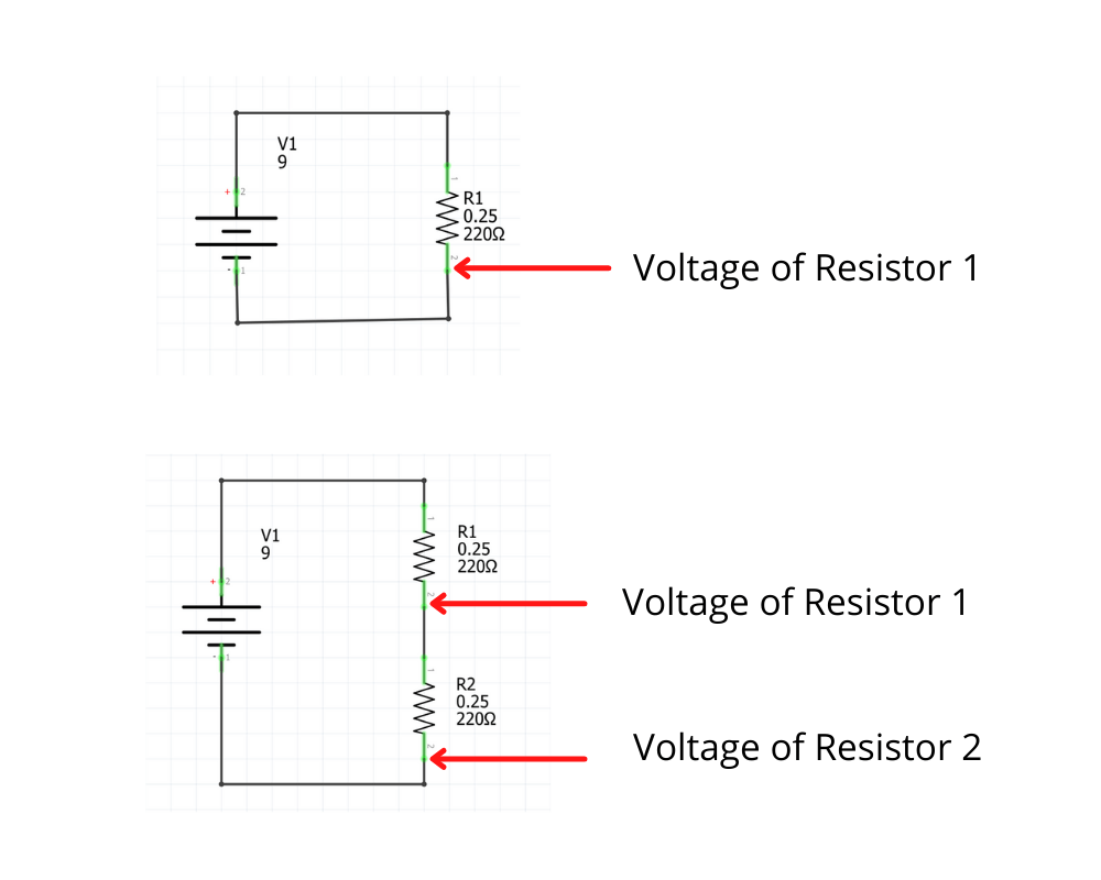
Left: All voltage is dropped across the single resistor. Right: The voltage is divided between two resistors connected in series.
The key principle: voltage is dropped, but current is not. In a series circuit, the current is the same through every component. The voltage decreases because the resistor converts electrical energy into heat — the current (flow of charge) is conserved.
Understanding Ohm's Law
Ohm's Law is the fundamental formula used to calculate the relationship between voltage, current, and resistance in any electrical circuit. It states:
V = I × R — Voltage equals Current times Resistance
By rearranging this formula, you can find any of the three values when you know the other two:
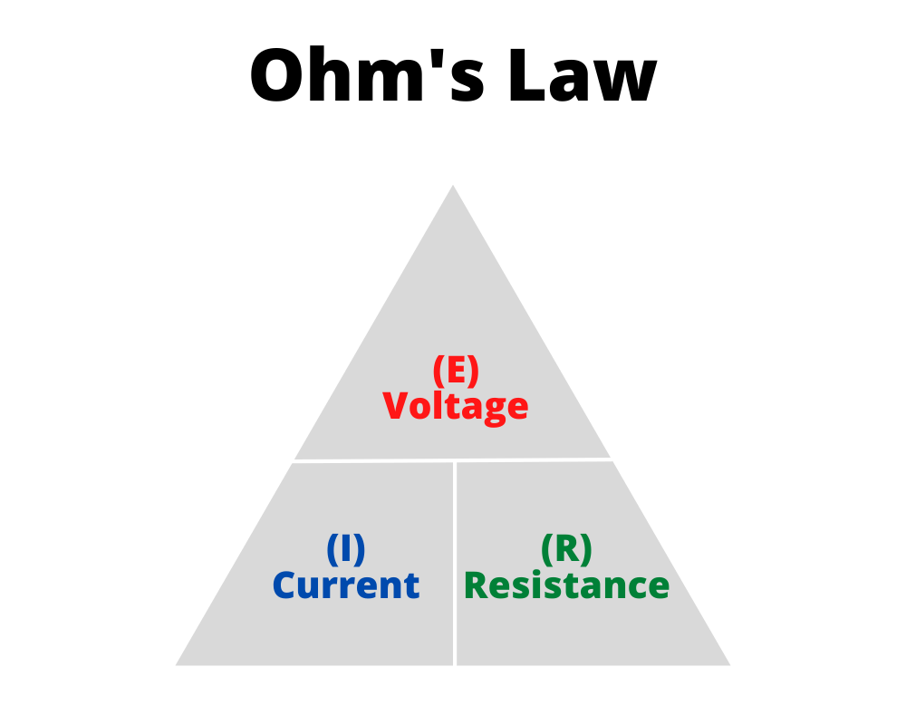
The Ohm's Law triangle — cover the value you want to find
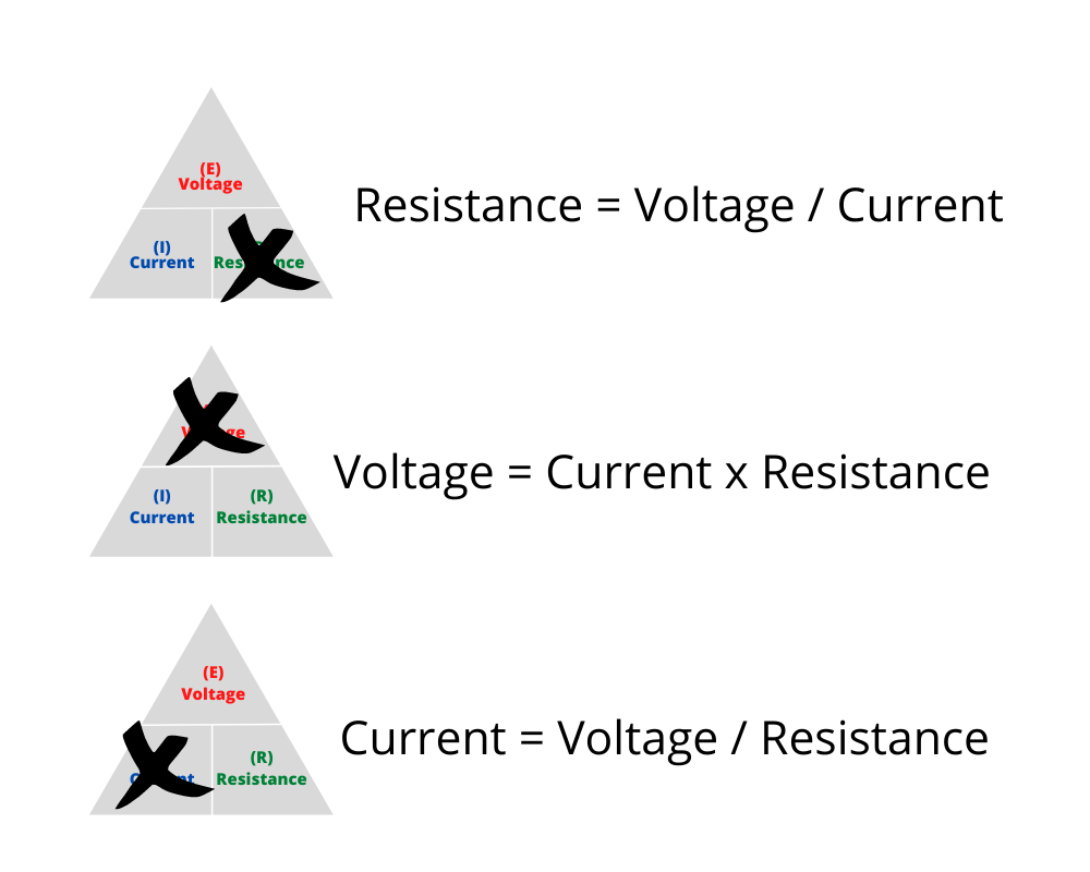
Three formulas derived from Ohm's Law
- Voltage = Current × Resistance (V = I × R)
- Current = Voltage ÷ Resistance (I = V / R)
- Resistance = Voltage ÷ Current (R = V / I)
You can use the Ohm's Law Calculator to quickly find any value.
How to Calculate Voltage Drop in a Series Circuit
What Is a Series Circuit?
A series circuit is a circuit where all components are connected end-to-end, forming a single path for current to flow. The current must pass through every resistor in order — there are no branches or alternative paths.
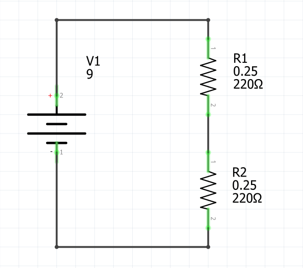
A series circuit with two resistors — current flows through both in the same path
Series circuits have two important principles that apply to voltage drop calculations:
Principle 1 — Current is constant: The current is the same through every component in a series circuit. If 0.02A flows through R1, then 0.02A also flows through R2. There is only one path for current to flow, so the same amount of charge passes through each resistor.
Principle 2 — Voltages add up (Kirchhoff's Voltage Law): The sum of all individual voltage drops in a series circuit equals the total supply voltage. This is known as Kirchhoff's Voltage Law (KVL) or Kirchhoff's Loop Rule:
Vtotal = V1 + V2 + V3 + ... + Vn
Series Circuit Formula for Total Resistance
To calculate voltage drops in a series circuit, you first need to find the total resistance. In a series circuit, the total resistance is simply the sum of all individual resistances:
Rtotal = R1 + R2 + R3 + ... + Rn
Step-by-Step: Calculate Voltage Drop in a Series Circuit
Follow these steps to calculate the voltage dropped across each resistor in a series circuit:
- Find the total resistance — add up all resistor values
- Calculate the current — use Ohm's Law: I = Vtotal / Rtotal
- Calculate each voltage drop — multiply the current by each individual resistance: V = I × R
- Verify your answer — check that all voltage drops add up to the supply voltage
Example 1: Two Equal Resistors
Given:
- Supply voltage = 9V
- R1 = 220Ω
- R2 = 220Ω
Step 1 — Total resistance:
Rtotal = 220Ω + 220Ω = 440Ω
Step 2 — Calculate the current:
I = V / R = 9V / 440Ω = 0.02A (20mA)
Step 3 — Voltage drop across each resistor:
VR1 = I × R1 = 0.02A × 220Ω = 4.5V
VR2 = I × R2 = 0.02A × 220Ω = 4.5V
Step 4 — Verify:
VR1 + VR2 = 4.5V + 4.5V = 9V ✓ (equals the supply voltage)
Because both resistors have the same value, the voltage is divided equally. Each resistor drops half of the total voltage. This is a basic voltage divider.
Example 2: Single Resistor
Given:
- Supply voltage = 12V
- R1 = 330Ω
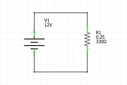
With a single resistor, the entire supply voltage is dropped across it. The voltage drop across R1 equals the source voltage: 12V.
The current flowing through the circuit:
I = V / R = 12V / 330Ω = 0.036A (36mA)
Example 3: Four Resistors in Series
Given:
- Supply voltage = 5V
- R1 = 33Ω
- R2 = 100Ω
- R3 = 4.7kΩ (4,700Ω)
- R4 = 220Ω
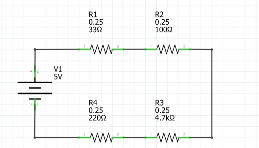
Step 1 — Total resistance:
Rtotal = 33Ω + 100Ω + 4,700Ω + 220Ω = 5,053Ω
Step 2 — Calculate the current:
I = V / R = 5V / 5,053Ω = 0.000989A (approximately 0.99mA)
Step 3 — Voltage drop across each resistor:
VR1 = 0.000989A × 33Ω = 0.033V
VR2 = 0.000989A × 100Ω = 0.099V
VR3 = 0.000989A × 4,700Ω = 4.649V
VR4 = 0.000989A × 220Ω = 0.218V
Step 4 — Verify:
0.033V + 0.099V + 4.649V + 0.218V ≈ 5V ✓
Notice how R3 (the 4.7kΩ resistor) drops almost all of the voltage — 4.649V out of 5V. This is because it has the largest resistance. In a series circuit, the largest resistor always drops the most voltage. The voltage dropped across each resistor is proportional to its share of the total resistance.
The Voltage Divider Network
A voltage divider is a simple series circuit with two resistors that produces an output voltage that is a fraction of the input voltage. It is one of the most commonly used circuits in electronics — used for level shifting, reading sensors, audio attenuation, and biasing transistors.
The voltage divider formula gives the output voltage directly, without needing to calculate the current first:
Vout = Vin × R2 / (R1 + R2)
For example, with a 12V supply, R1 = 10kΩ, and R2 = 10kΩ:
Vout = 12V × 10,000 / (10,000 + 10,000) = 12V × 0.5 = 6V
Try different values with the Voltage Divider Calculator.
Voltage Drop in a Parallel Circuit
In a parallel circuit, each resistor is connected across the same two nodes — each branch has its own separate path for current to flow. This changes the rules significantly compared to a series circuit.
The key principle of parallel circuits: the voltage across each branch is the same. Every resistor connected in parallel sees the full supply voltage. There is no voltage division between parallel resistors — the voltage dropped across each resistor equals the source voltage.
So if your supply voltage is 9V and you have three resistors connected in parallel:
- Voltage across R1 = 9V
- Voltage across R2 = 9V
- Voltage across R3 = 9V
What does change in a parallel circuit is the current. The total current from the supply splits between the branches, with more current flowing through lower-resistance paths. The current through each resistor is calculated using Ohm's Law:
Ibranch = V / Rbranch
Example: Three Resistors in Parallel
Given:
- Supply voltage = 12V
- R1 = 100Ω
- R2 = 220Ω
- R3 = 470Ω
Voltage across each resistor: All three resistors see the full 12V.
Current through each branch:
IR1 = 12V / 100Ω = 0.12A (120mA)
IR2 = 12V / 220Ω = 0.055A (55mA)
IR3 = 12V / 470Ω = 0.026A (26mA)
Total current from the supply:
Itotal = 0.12A + 0.055A + 0.026A = 0.201A (201mA)
The total resistance of a parallel circuit is always less than the smallest individual resistor. It is calculated using this formula:
1/Rtotal = 1/R1 + 1/R2 + 1/R3
1/Rtotal = 1/100 + 1/220 + 1/470 = 0.01 + 0.00455 + 0.00213 = 0.01668
Rtotal = 1 / 0.01668 = 59.95Ω
Verify: Itotal = V / Rtotal = 12V / 59.95Ω = 0.200A ≈ 0.201A ✓
Voltage Drop Calculations in Series and Parallel Circuits
Real circuits often combine both series and parallel connections. To calculate voltage drops in a combined circuit:
- Identify which resistors are in series and which are in parallel
- Simplify — calculate the equivalent resistance of the parallel section
- Treat the simplified circuit as a series circuit
- Calculate the total current using Ohm's Law
- Find the voltage dropped across each section
Example: Series-Parallel Combination
Given a circuit with R1 = 100Ω in series with a parallel combination of R2 = 220Ω and R3 = 330Ω, powered by a 9V supply:
Step 1 — Equivalent resistance of R2 ∥ R3:
Rparallel = (R2 × R3) / (R2 + R3) = (220 × 330) / (220 + 330) = 72,600 / 550 = 132Ω
Step 2 — Total resistance:
Rtotal = R1 + Rparallel = 100Ω + 132Ω = 232Ω
Step 3 — Total current:
I = 9V / 232Ω = 0.0388A (38.8mA)
Step 4 — Voltage drops:
VR1 = 0.0388A × 100Ω = 3.88V (dropped across R1)
Vparallel = 0.0388A × 132Ω = 5.12V (dropped across the parallel section)
Both R2 and R3 see the same 5.12V across them (because they are in parallel), but the current splits: more current flows through R2 (the lower resistance) than R3.
Verify: 3.88V + 5.12V = 9V ✓
Kirchhoff's Voltage Law and Ohm's Law
Two fundamental laws govern voltage drop calculations in any electrical circuit:
Ohm's Law (V = I × R) tells you the voltage dropped across a single resistor when you know the current and resistance. This is the formula you use for each individual resistor.
Kirchhoff's Voltage Law (KVL) — also called Kirchhoff's Loop Rule — states that the sum of all voltage drops and voltage sources around any closed loop in a circuit equals zero. In practical terms for a simple series circuit:
Vsupply = VR1 + VR2 + VR3 + ... + VRn
KVL is your verification tool. After calculating each voltage drop using Ohm's Law, add them up. If they equal the supply voltage, your calculations are correct. If they don't, check your work.
These two laws — Ohm's Law for individual calculations and Kirchhoff's Voltage Law for verification — are all you need to calculate voltage drops in any resistive circuit, no matter how many resistors are involved.
The Potential Difference Between Two Points
Voltage drop and potential difference refer to the same thing — the difference in electrical potential between two points in a circuit. When we say "the voltage drop across a resistor is 4.5V," we mean the potential difference between the two terminals of that resistor is 4.5 volts.
The potential at any point in a circuit is measured relative to a reference point, typically ground (0V). As current flows through resistors connected in series, the potential decreases step by step. After the last resistor, the potential reaches ground.
For example, in a 9V circuit with two equal 220Ω resistors in series:
- Before R1: potential = 9V
- Between R1 and R2: potential = 4.5V (after dropping 4.5V across R1)
- After R2: potential = 0V (after dropping another 4.5V across R2)
This step-by-step decrease in potential is what makes series circuits useful as voltage dividers — you can tap the voltage at any point between resistors to get a specific voltage level.
How to Measure Voltage Drop Across a Resistor
To measure the voltage dropped across any resistor in a circuit, you need a multimeter:
- Set the multimeter to DC voltage mode (V with a straight line, not the wavy AC symbol)
- Connect the red probe to the side of the resistor closer to the positive terminal of the power supply
- Connect the black probe to the other side of the resistor
- Read the voltage displayed — this is the voltage drop across that resistor
Important: The multimeter must be connected in parallel (across) the resistor, not in series. If you break the circuit and insert the multimeter in series while in voltage mode, you will get an incorrect reading and could damage the meter.
You can verify your calculations by measuring the voltage across each resistor and confirming that the sum of all measured voltage drops equals the supply voltage (Kirchhoff's Voltage Law). Small differences are normal due to resistor tolerance — a resistor with ±5% tolerance may have an actual resistance slightly different from its labeled value. Read more about resistor color codes and tolerance.
Summary: Voltage Drop Calculations
Here are the key formulas and principles for calculating voltage drops across resistors:
| Concept | Formula |
|---|---|
| Voltage drop (Ohm's Law) | V = I × R |
| Current in a circuit | I = V / R |
| Total resistance (series) | Rtotal = R1 + R2 + ... + Rn |
| Total resistance (parallel) | 1/Rtotal = 1/R1 + 1/R2 + ... + 1/Rn |
| Kirchhoff's Voltage Law | Vsupply = V1 + V2 + ... + Vn |
| Voltage divider output | Vout = Vin × R2 / (R1 + R2) |
| Parallel voltage | Same across all branches |
Use the Voltage Drop Calculator to quickly calculate the voltage drop across any resistor, or the Ohm's Law Calculator to find voltage, current, or resistance. If you are working with Arduino arrays to control multiple LEDs, understanding voltage drop is essential for sizing your resistors correctly.